









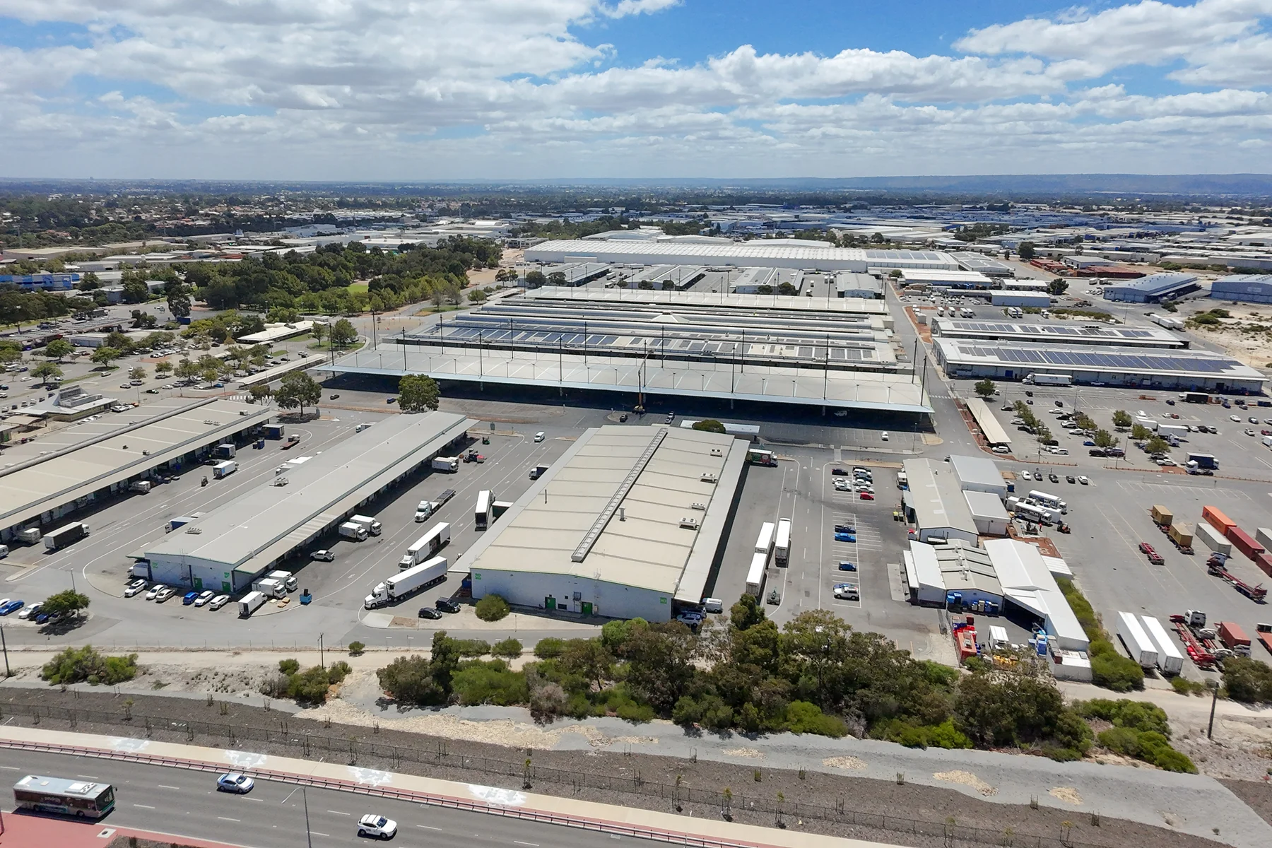
ResultSunlock and the project team could plan panel positions and fixings around nine assessed roof areas, with site-specific structural conditions clearly defined.
The challenge
One solar project. Different roof conditions.
The precinct’s roofs had different heights, support arrangements and structural capacities. A mounting layout suitable for one area could not simply be repeated across the site.
Our role was to establish what each roof could support and turn those findings into installation requirements the project team could follow.
What we did
Assess the structure and the solar mounting together.
Review the existing roofs
We reviewed structural drawings, inspection information and site photographs to establish member sizes, spans, spacing and connections. Where drawings were unavailable, measured site information informed the assessment.
Check roof capacity and wind loads
We checked the roof supports for strength and deflection, and assessed wind demands across the roof zones. The findings identified suitable panel locations and areas to keep clear.
Assess the Sunlock mounting systems
We checked rails, mounting feet and screw connections against the roof conditions. The certificates defined permitted rail directions, support arrangements and fixing requirements.
Review layouts and document the conditions
We revisited roof-zone definitions where panel positioning constrained the layout, then documented the assessed arrangements and limits in the structural certificates.
The problems we solved
Make the installation requirements specific.
Match panel positions to available support
Some locations required panels to sit above rafters. We identified where that arrangement was needed so the layout reflected the structure beneath it.
Account for different mounting demands
Rail direction, rail count and mounting-foot selection affected the loads transferred to the roof. We assessed the options and defined what was permitted in each zone.
Set clear installation limits
The certification identified no-panel zones, rail overhang limits and continuity requirements, giving the team a defined arrangement to follow.
The assessment inputs
Engineering grounded in the existing structure.
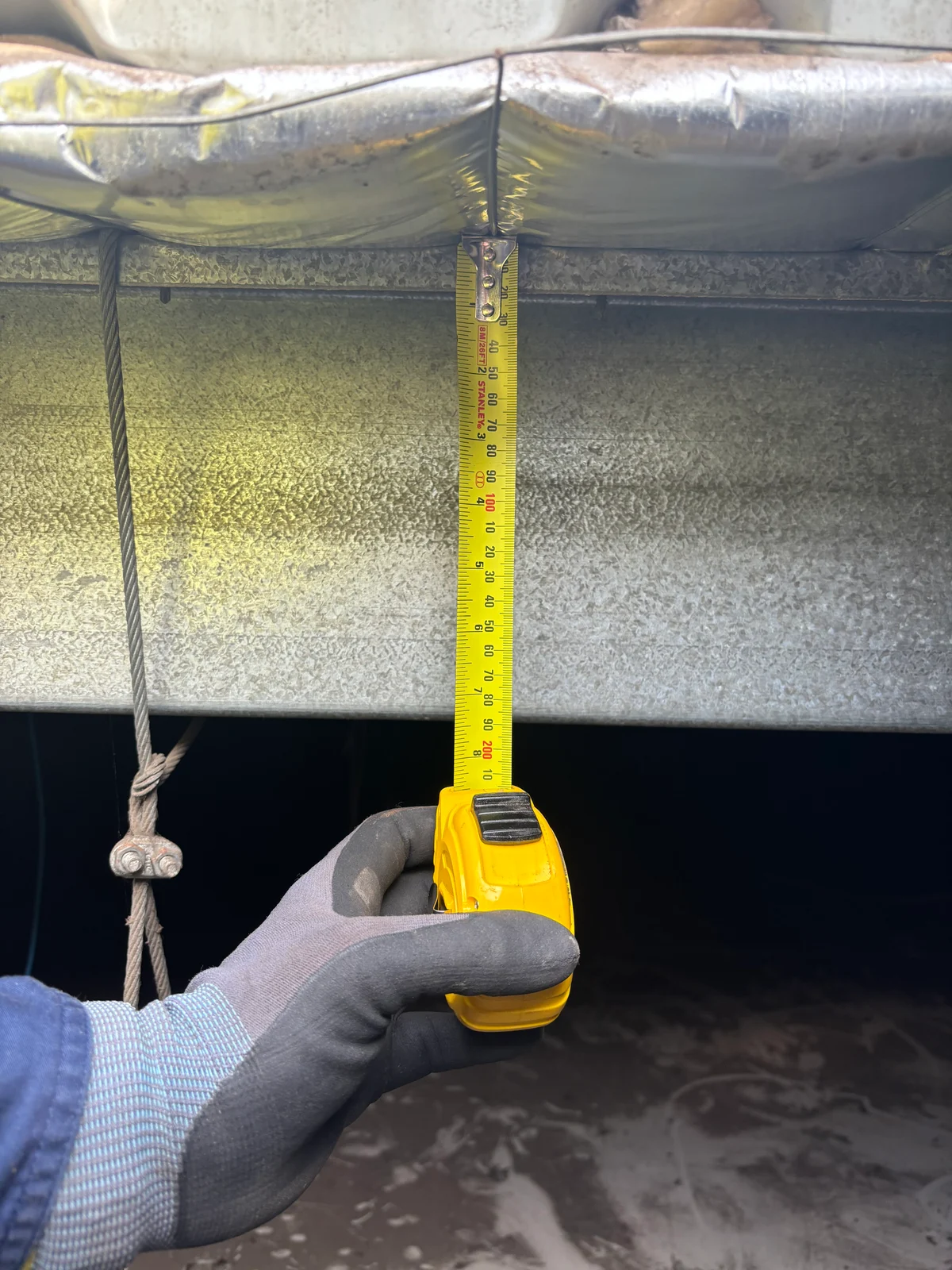
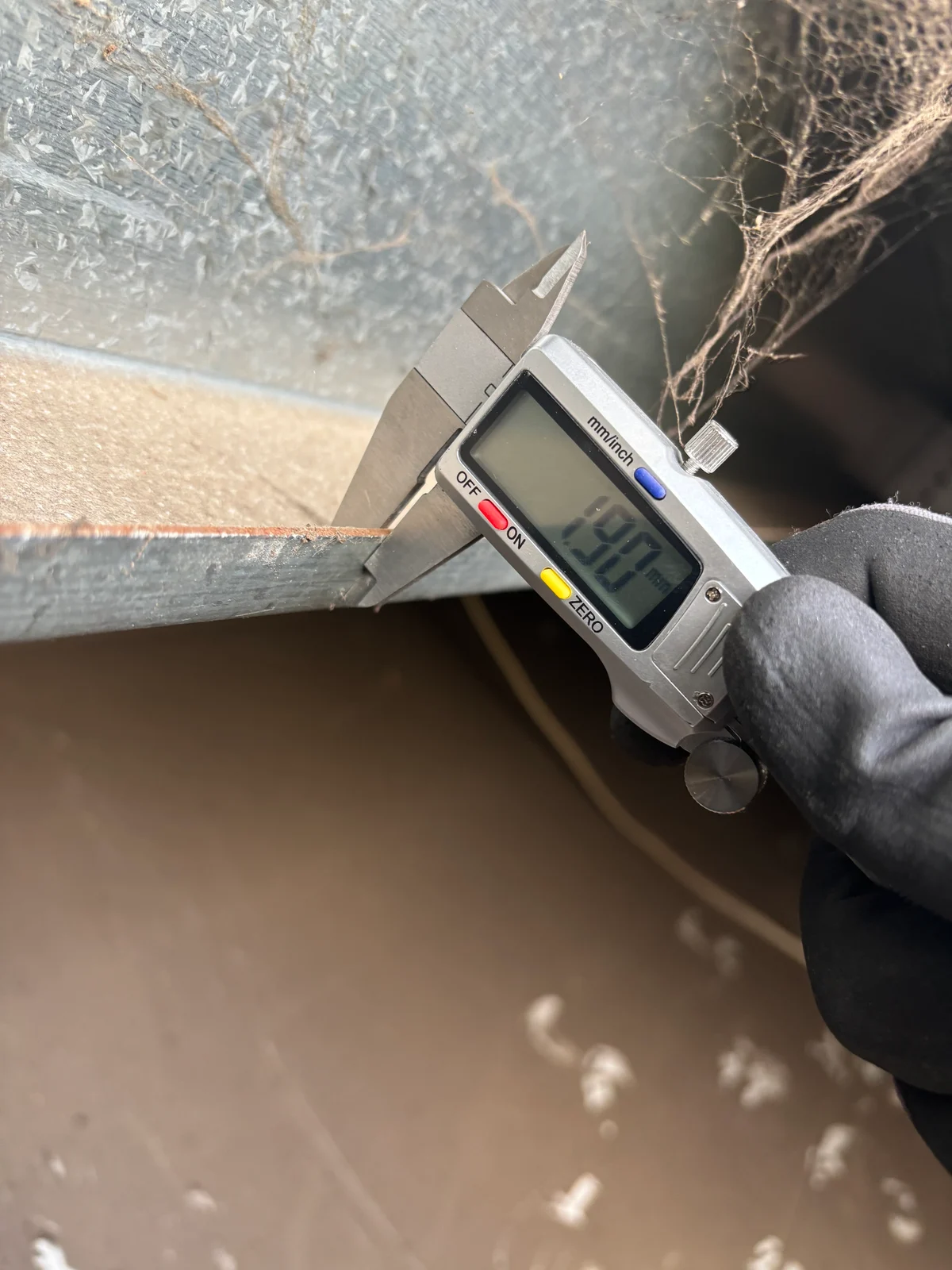
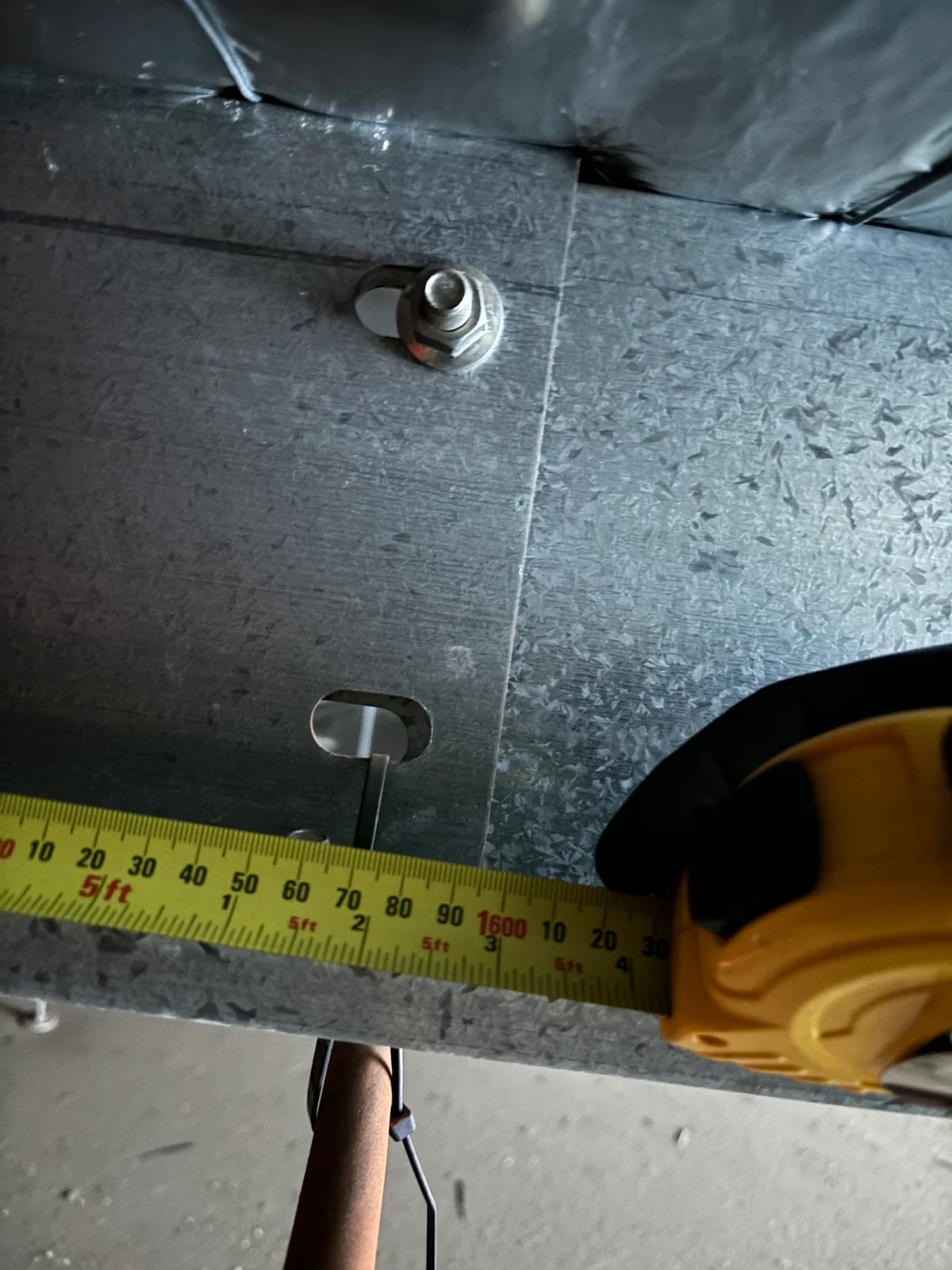
Site measurements and photographs helped verify the roof details used in the calculations.
Result for the client
Plan the installation around each roof
Sunlock and West Australian Alternative Energy gained a structural basis for planning solar across nine roof areas. The team could match the proposed panel layout and mounting arrangement to the support available beneath each part of the roof.
- Position panels around the structure: the findings identified where panels needed to sit above rafters and which areas had to remain clear.
- Use the assessed mounting arrangement: the certificates defined permitted rail directions, mounting feet, fixing requirements and installation limits.
- Work from documented conditions: roof assessments and site-specific array-frame certification recorded the structural requirements for the proposed installation.
The certification applied to the assessed roof supports, frames and connections, subject to its stated conditions. Electrical design and grid approvals remained outside this scope.
Planning solar across an existing site?
Send the proposed layout, mounting details and available roof information.